-
Product Classification
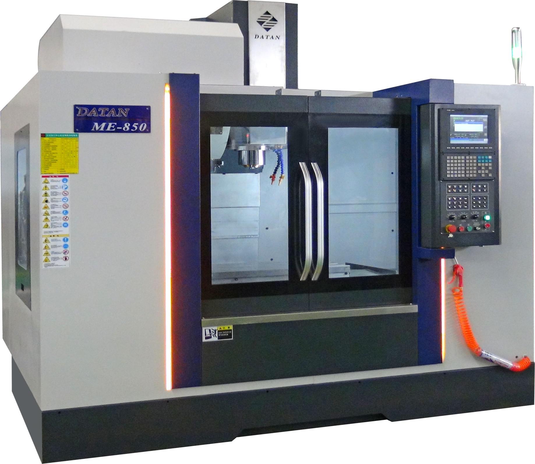
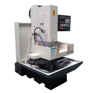
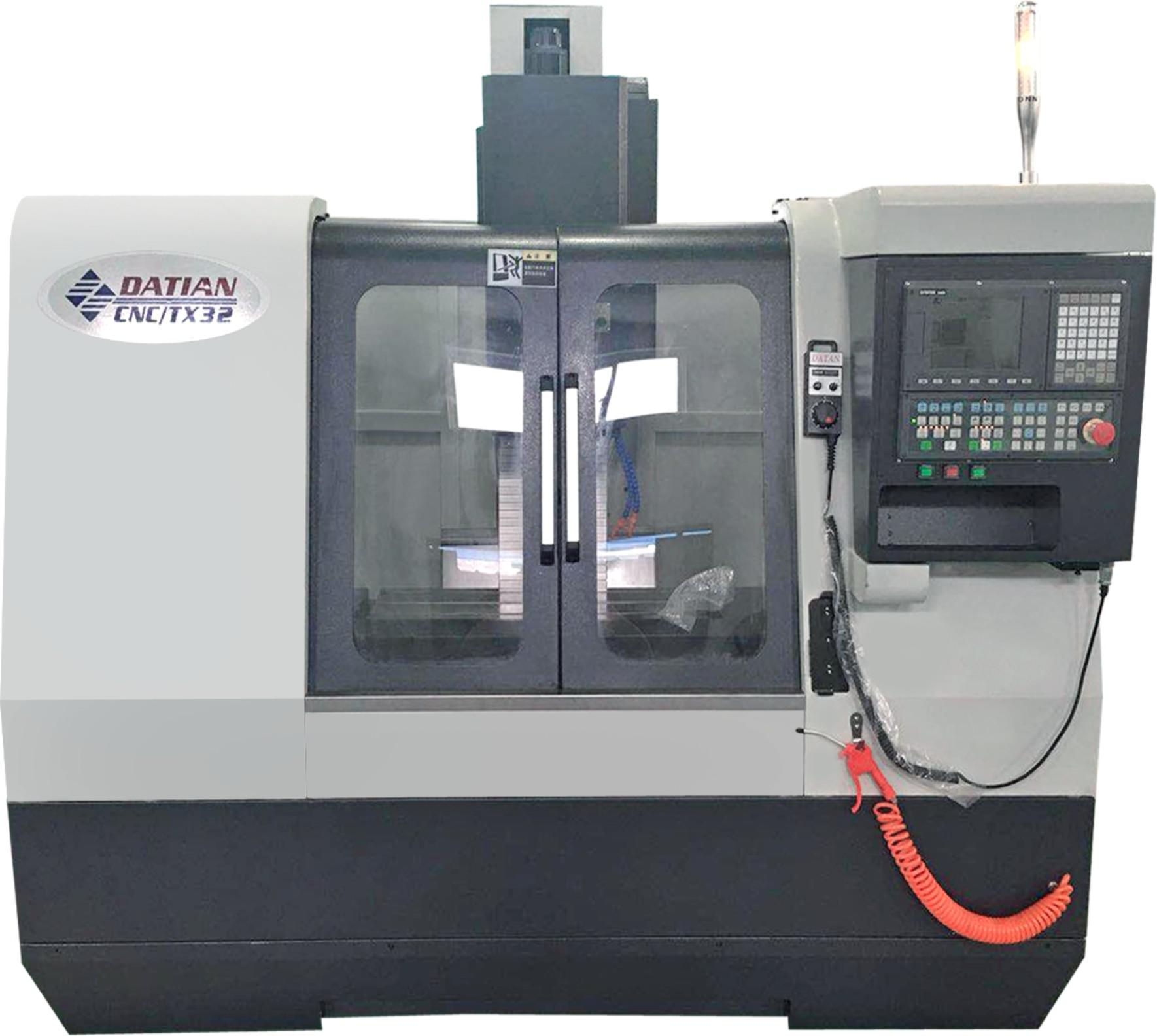
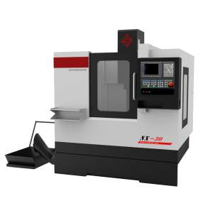
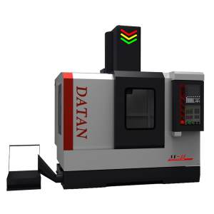
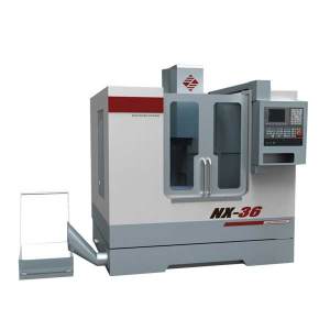
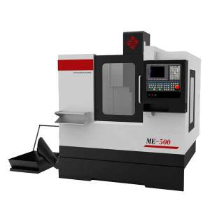
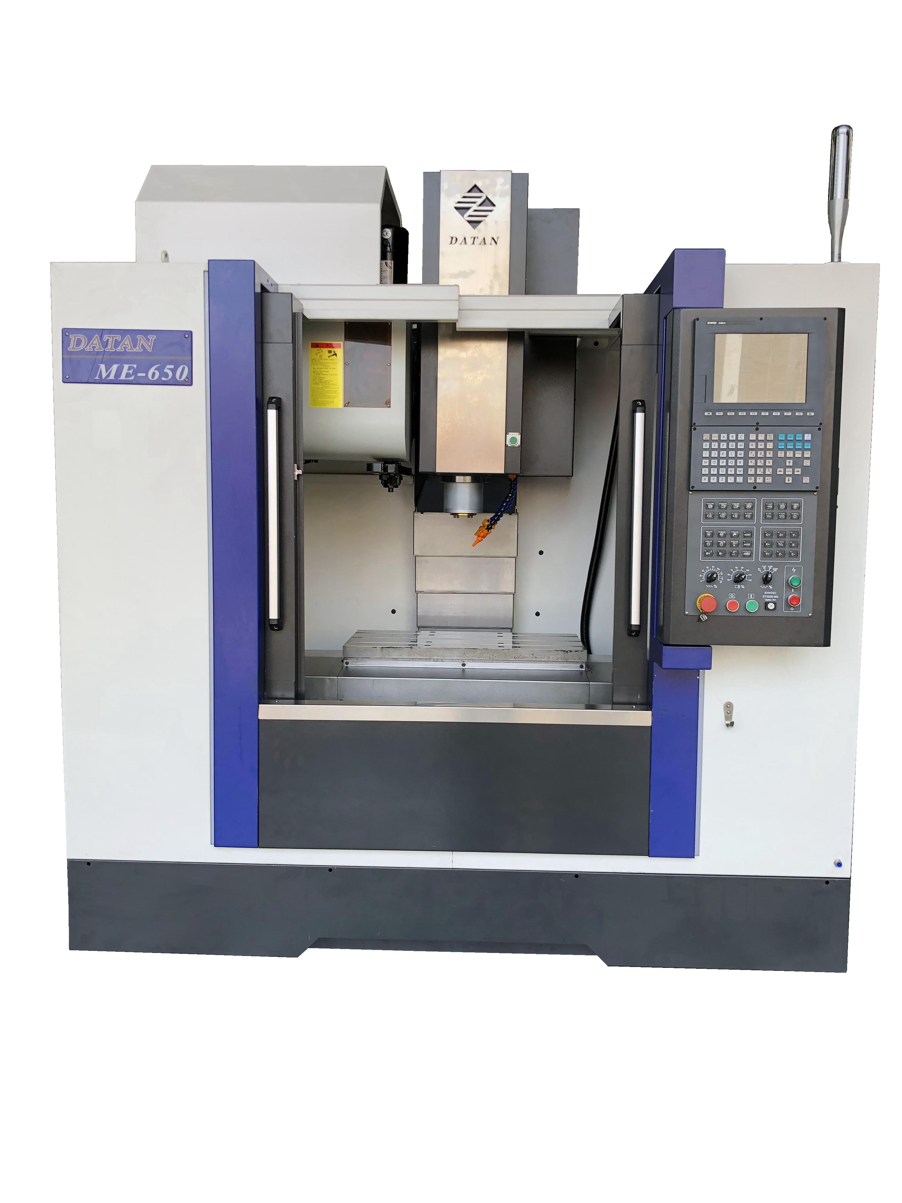
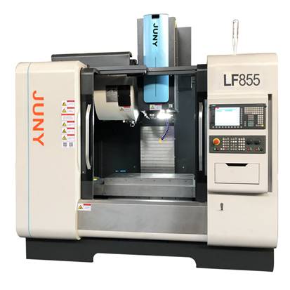
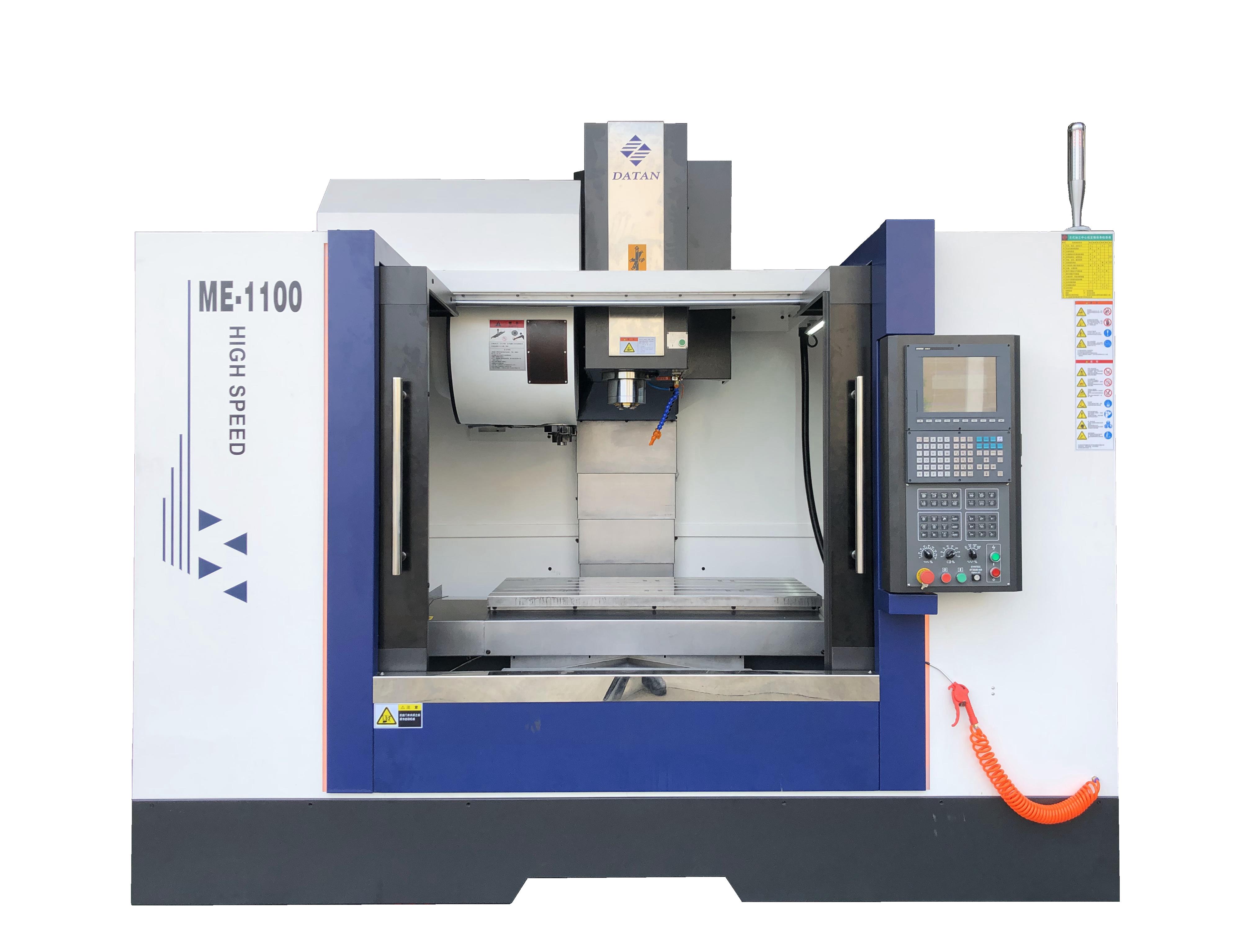
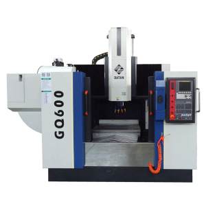
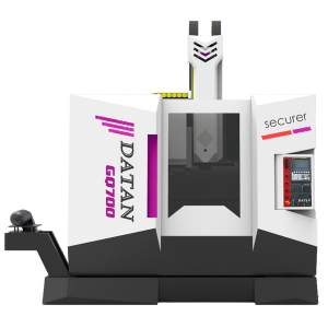
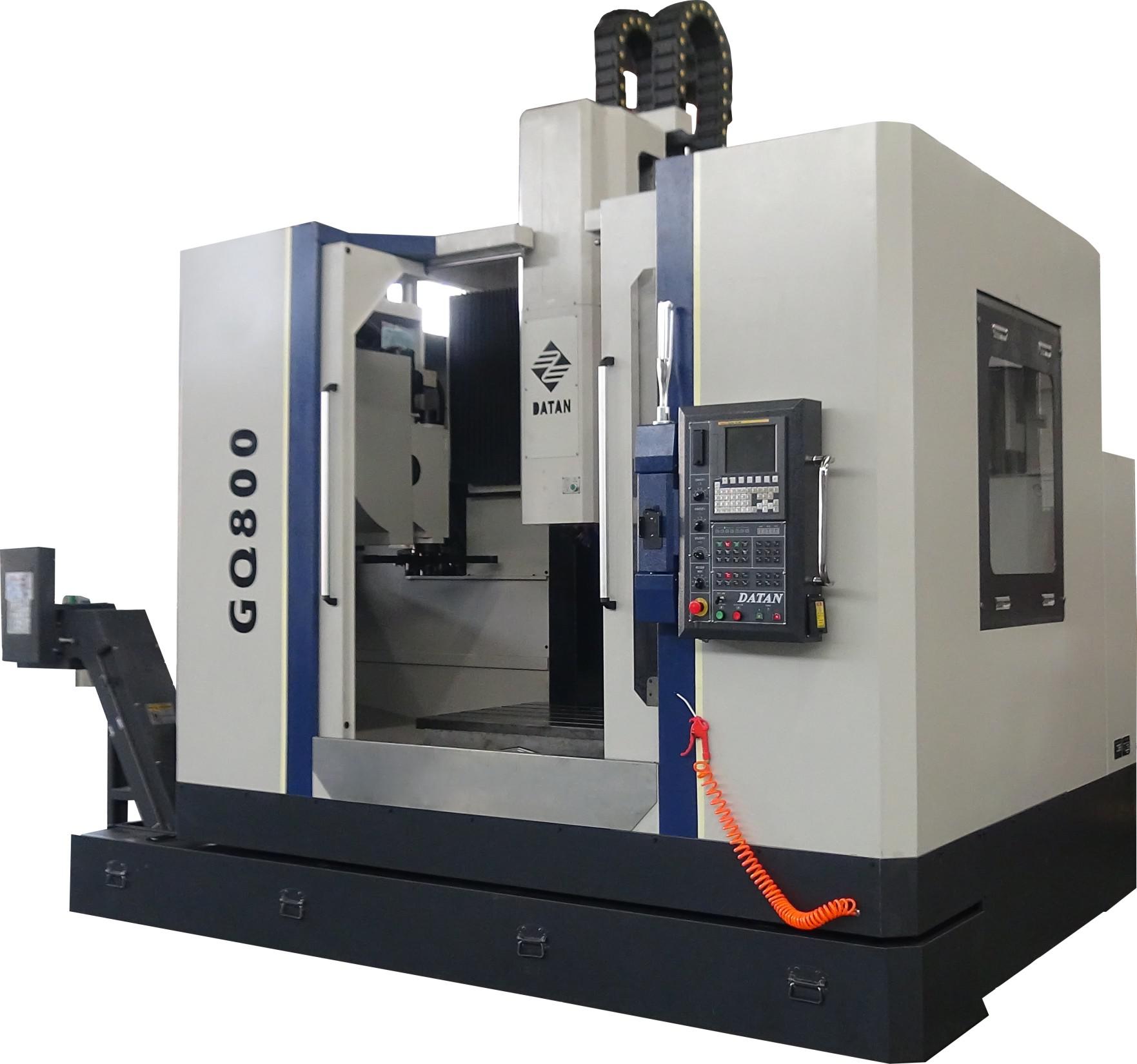
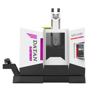
- MILLING
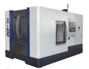
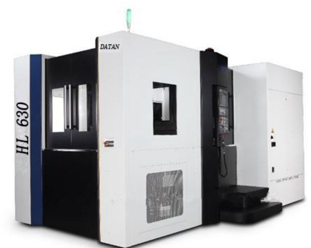
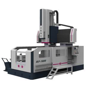
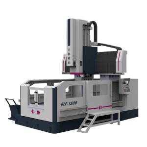
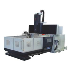
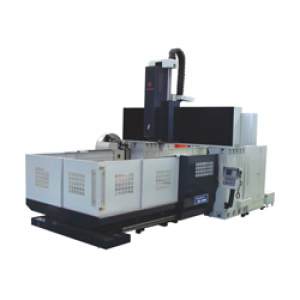
- GANTRY
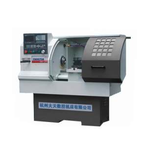
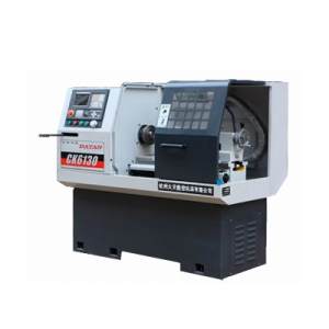
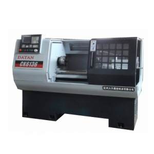
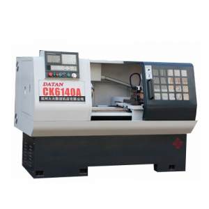
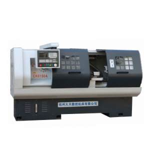
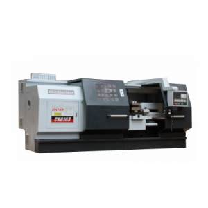
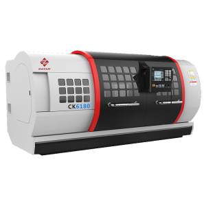
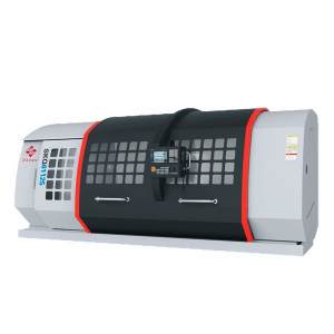
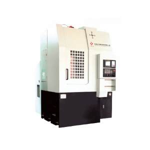
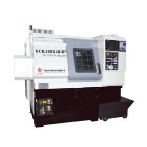
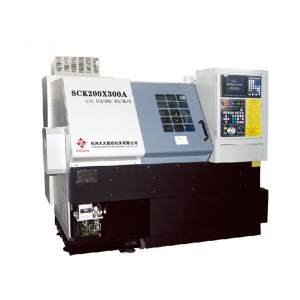
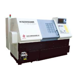
- CNC LATHE
-
Optional Configuration
-
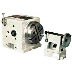 FK15 Series NC Dividing Head
-
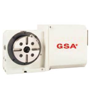 NC Indexing Head
-
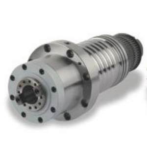 Complete Spindle
-
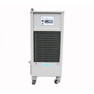 Spindle Oil Cooler
-
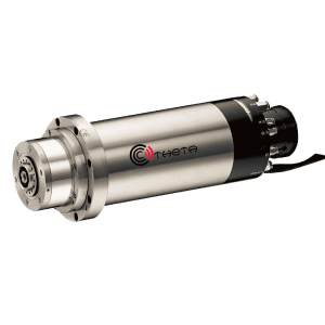 Electric Spindle
-
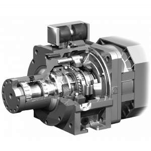 Spindle Reduction Gear Box
-
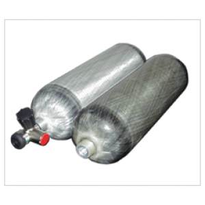 Gas Cylinder
-
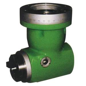 Side Milling Head
-
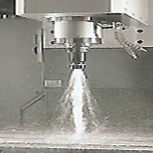 Coolant Trough Spindle
-
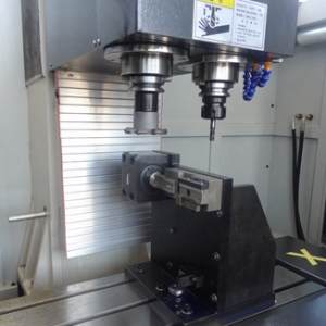 Multiple Spindle
-
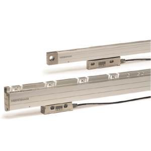 Grating Ruler
-
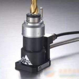 Tool Auto-checking Instrument
-
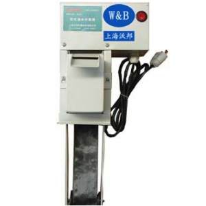 Oil Water Separator
-
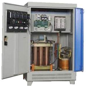 Automatic AC Voltage Regulator
-
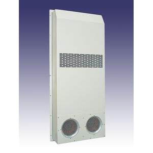 Cabinet Air-Conditioner
-
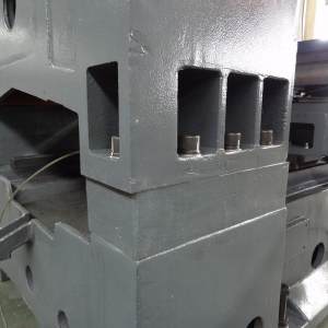 Column Heightening
-
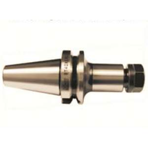 ER Spring Collect Chuck Systen
-
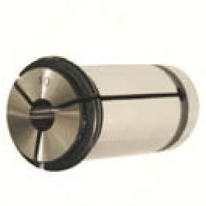
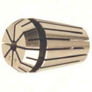 cnc milling machine parts-ER Spring Colllets
-
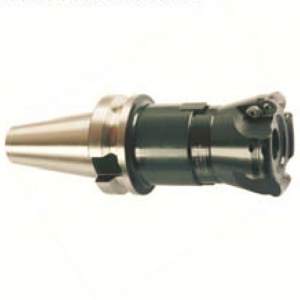
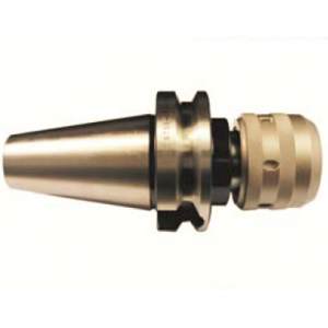 BT-MLC Milling Chuck
-
 Power Milling
-
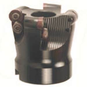
 BT-FMA Face Mill Holder
-
 HME Rotary Edge Finder
-
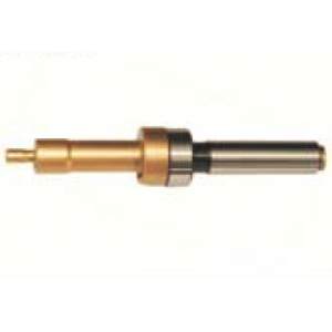 HME Rotary Edge Finder
-
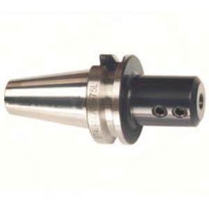 SLA Side Lock End Mill Holder
-
 SD Fast Bit Discard
-
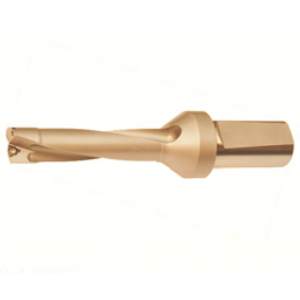
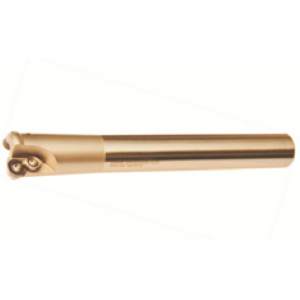 EMRW Round Dowel End Mill
-
 EMRW Round Dowel End Mill
-
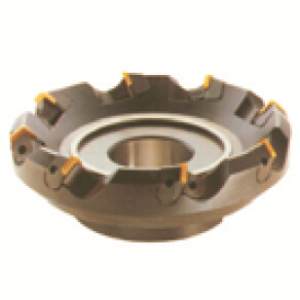
 TRS Round Dowel Face Mill
-
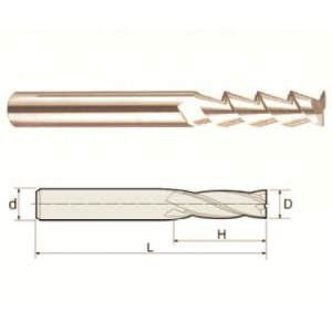
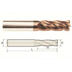 4 Flutes Square End Mills
-
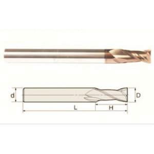 2 Flutes Square End Mills
-
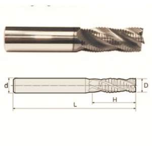 4 Flutes Roughing End Mills
-
 For Aluminum Alloy Processing 2 Flutes Square End Mills
-
 H-BIT Double-edged Sword Coarse Sugar Kong
-
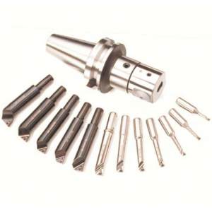 NBJ16 Smail Diameter BORING BAR / HBOR
-
-
Case
-
Video
-
Service
-
About Us